Full Bit Adder Diagram
Binary adder and subtractor circuits: half and full adder, subtractor Full adder circuit diagram The answer is 42!!: four bit full adder tutorial
Full Adder Circuit Diagram
Digital logic design: full adder circuit [diagram] logic diagram 4 bit adder Full adder circuit 4 bit
Adder full half circuit carry ripple bit schematic diagram gate truth table delay doubt xor without electronics electrical representation shown
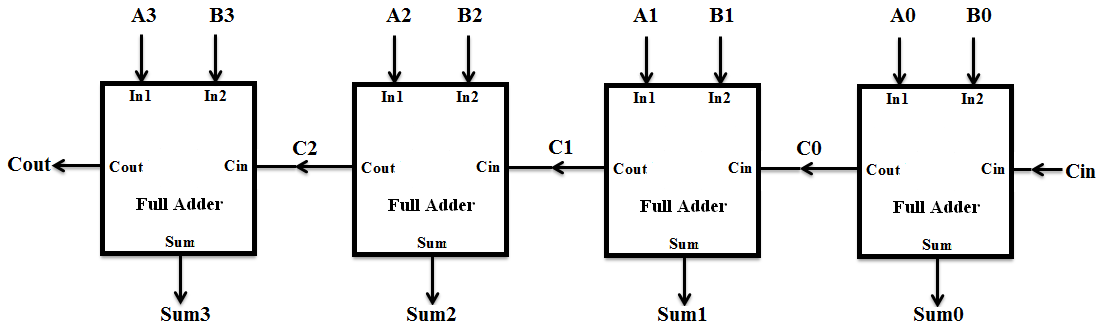
4 bit binary adder circuit diagram4 bit binary incrementer 1 bit full adder circuit diagramFull adder logic circuit diagram.
4 bit parallel adder using full adders4-bit adder subtractor 4 bit full adder circuit diagramAdder subtractor bit alu binary if gates chapter performs ppt powerpoint presentation xor inverters programmable act.

How to construct truth tables logic gates
Explain 5-bit adder and subtractor circuitsDownload 4 bit adder circuit stick and logic diagram Adder parallel addersFull adder circuit diagram using ic.
Adder circuit full logic using digital boolean implementation diagram implement function[diagram] logic diagram of 4 bit full adder 4 bit adder subtractor4 bit ripple carry adder circuit diagram.

4-bit full adder circuit diagram
8 bit full adder circuit diagramWhat is half adder and full adder circuit? 4 bit adder diagramCircuit diagram 2 bit full adder.
Four bit parallel adder using full adderBit binary bits output geeksforgeeks incremented Adder circuit truth binary adders sum implementAdder circuit full table truth logic its gates theory construct elcho seat visit.

Adder bit full four logic gates byte 4bit nand boolean not nor values possible possibilities hold answer trick function known
4-bit full adder circuit diagramAdder logic 4 bit binary subtractor circuit diagram4 bit full adder circuit, truth table and symbol. implement 4 bit.
2 bit adder circuit diagram .


